Programming ATtiny85 with ArduinoISP
Download the Tiny-core here: code.google.com/p/arduino-tiny/
Follow the instructions in the readme.txt file
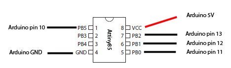
Connect your Arduino to the Attiny according to the picture above
- Upload the ArduinoISP to the Arduino dont't connect the capacitor yet.
- Connect a 10 µF capacitor from reset to ground on the arduino (negative side to ground)
- Open the blink sketch and change pin13 to pin3
- select Tools -> board -> Attiny85@1MHZ (leave the serial port as it is)
- Select Tools -> Programmer -> Arduino as ISP
- Select File -> upload using programmer
- Connect a LED with resitor to pin PB3
- Now you should have a blinkining Led on your Attiny85
Note the factory default is 1MHz, if you want to run 8MHz, use this:
Select Board -> Attiny85@8MHZ
select Programmer -> Arduino as ISP
Select ->Burn bootloader
Note: this step do not burn a bootloader to your chip, it is only used to set the fuses to another clock-speed.
PWM pins are PB0, PB1 and PB4
Example: analogWrite(4,127); Pwm on pin PB4, 50% duty cycle
Analog (ADC) pins are PB2 (A1), PB4 (A2) and PB3 (A3) (physical 7,3 and 2)
Example: val=analogRead(2); Reads ADC value on pin PB4
Useful links for Atiny85:
Coding Badly's TinyISP reply #33
Coding Badly's TinyTuner
Coding Badly's TinyTuner2
Servo library for attiny85